Designing for the Permold process is very intuitive. As in most casting processes, draft, radius, and wall thickness are the main design elements critical to good castability. Our engineering staff is available around the clock to help you get the most out of your investment. Gupta Permold always meets and/or exceeds the Aluminum Association Standards for Permanent Mold Castings which are outlined in the table below for your convenience.
Contact Gupta Permold today for your full copy.
| Linear Tolerance | ||||
|---|---|---|---|---|
| Range (in.) | ||||
| From | To | Base Tolerance | Each Add'l In. | |
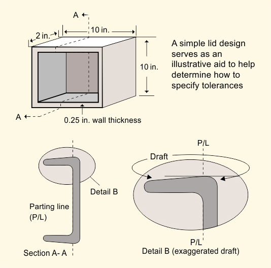
| One Side of Parting Line (Basic): | 0 | 1 | +/-.015 | +/-.002 |
| Across Parting Line (Add'l): | Tolerance is added as a function of projected parting face surface area. | |||
| 0 in2 | 10 in2 | +/-.010 | ||
| 10 in2 | 50 in2 | +/-.015 | ||
| 50 in2 | 100 in2 | +/-.020 | ||
| Flatness | ||||
| Greatest Dimension (in.) | ||||
| From | To | Base Tolerance | Each Add'l In. | |
| 0 | 6 | +/-.020 | +/-.002 | |
| Concentricity | ||||
| Range (in.) | ||||
| From | To | Base Tolerance | Each Add'l In. | |
| Same Plane: | 0 | 5 | +/-.025 | +/-.003 |
| Across Parting Line: | 0 | 10 | +/-.040 | +/-.003 |
| Machine Stock Allowance | ||||
| Greatest Dimension (in.) | ||||
| From | To | Stock Amount | ||
| 0 | 12 | 1/16 | ||
| 12 | 18 | 3/32 | ||
| 18 | 24 | 1/8 | ||
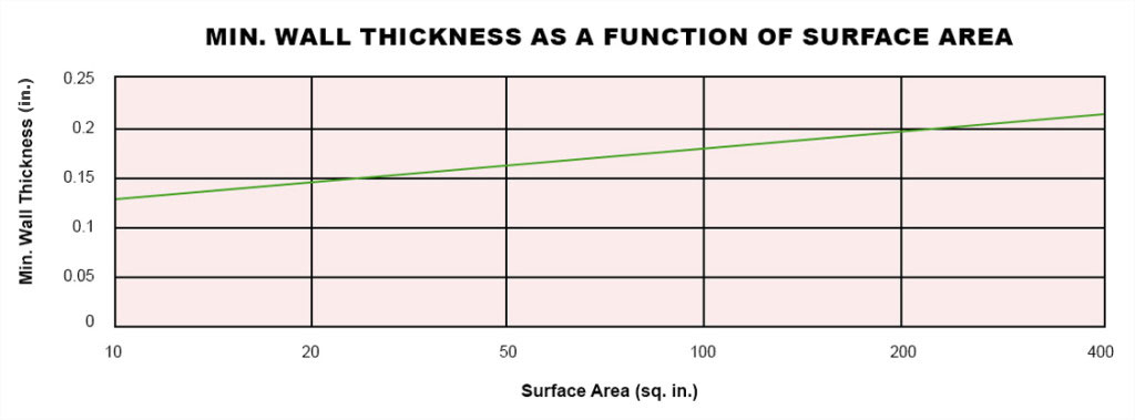
| Wall Thickness | ||||
 |
||||
| *Note: Wall thickness values represented are minimums for castings of minimal complexity. Thickness values need to be increased as part complexity rises. Please consult Gupta Permold Engineering for specific job analysis. | ||||
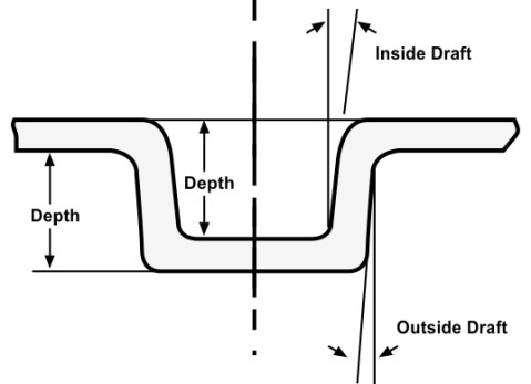
| Draft Requirements
Draft decreases inversely with length of draw. Note; the below amounts are simply industry guidelines and can be tightened in many cases. Also, additional draft extends mold life and makes better, cleaner castings. Contact us for details |
||||
| Draft Requirements for Inside & Outside Walls | Depth (in.) | Inside Draft (degrees) | Outside Draft (degrees) | |
 |
0.03 - 0.125 | 20 | 10 | |
| 0.126 - 0.5 | 15 | 7 | ||
| 0.501 - 1 | 10 | 5 | ||
| 1.01 - 6 | 5 | 3 | ||
| 6-12 | 1.5 | 1.5 | ||
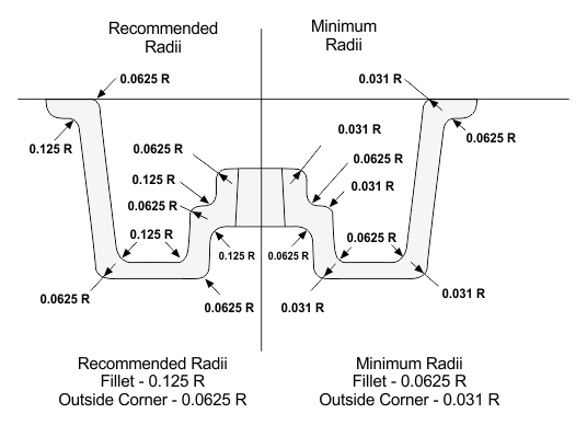
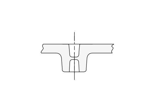
| Fillets & Radii
Razor sharp corners not possible (in all foundry). For two wall of thickness "t," designer should consider optimal radius of R=t. For Radii Between 2 non-uniform walls, designer should use the average wall thicknesses being connected, i.e. R= (T + t)/2. |
||||
 |
||||
| Cored Hole Diameter vs. Depth Draft | ||||
| Diameter (in.) | Max. Depth (in.) | Draft / Side (degrees) | ||
 |
0.25 | 0.125 | 15 | |
| 0.25-0.5 | 0.25 | 8 | ||
| 0.5 - 1 | 1 | 5 | ||
| 1 - 2 | 3 | 3 | ||
| 2-4 | 6 | 2 | ||
Have a project in mind? Send us your requirements and we'll get back to you.